30V4060
Reliance Electric
30V4060
Reliance Electric
Description
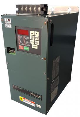
The 30V4060 GV3000 Series Drive by Reliance Electric. New & Remanufactured. Technical Specs, Fault Codes, Wirinig & More.
The 30V4060 is a GV3000 AC Drive manufactured by Reliance Electric. Although now obsolete Distribution Cache continues to supply the 30V4060 as well as other drives in this series. The 30V4060 is a 30 HP 380-460 VAC +/-10% AC Drive with a 1 / 12 Nema Rating. This series of drives comes in three distinct types, NEMA Style, Power Module Style, and Bookshelf Style. The 30V4060 is a NEMA Style Drive with the physical dimensions 460 mm / 18.1 x 405 mm / 15.9 x 354 mm / 13.6 and a weight of 23 kg / 51 lbs. Certain models come equiped with a CE Emission Filer. Let Distribution Cache be your go-to source for the GV3000 series and trust that our unparralleled warranty will keep you up and running for years to come.
| MPN | 30V4060 |
|---|---|
| HP | 30 HP |
| Input Voltage | 380-460 VAC +/-10% |
| NEMA Rating | 1 / 12 |
| Input KVA | 35 |
| Input Amps | 44 |
| Output Amps at 2Kz | 39 |
| Output Amps at 4Kz | 39 |
| Output Amps at 8Kz | 39 |
| Series | GV3000 drives |
| Dimensions | 460 mm / 18.1 x 405 mm / 15.9 x 354 mm / 13.6 |
| Weight | 23 kg / 51 lbs |
Distribution Cache Shipping Info and Options
Shipping Carriers: Here at Distribution Cache we ship using UPS, FedEx, DHL, or TNT. In most cases we get very competitive rates based on our volume and will be happy quote shipping cost to your location upon request. We also know that many customers would prefer to ship collect on their own account numbers and welcome this option.
Shipping Blind: We recognize that many of our customers intend to re-sell the product to their end user. We respect our customer’s relationships with their clients and offer blind shipping as an option to ensure that the package arrives in the most clandestine way possible.
Shipping Process: We take pride in the way we package your order and spare no cost in making sure that it arrives safely at your facility. In the case of new parts, we are always sure to package the factory box inside another larger box for safe transit. For reconditioned parts we often use Distribution Cache customized packaging that is specially made to protect the products from the bumps and falls present during shipment.
Shipping Options:
Next Day Air Early AM - This service is the fastest overnight delivery option available. For most locations the package will be guaranteed by 8:30AM.
Next Day Air – This service guarantees delivery by 10:30AM and is the most frequently used option for overnight shipments.
Next Day Air Saver – This cost saving overnight alternative guarantees delivery by 3PM the next day.
2nd Day Air – For domestic shipments that would take 3-5 days if shipped via Ground, sometimes having the order in 2 days is a great way to go
Ground – Ground is the most inexpensive shipping option provided. Please ask if we are doing a “free domestic ground” shipping promotion on your order. We often provide free ground shipping on larger orders.
Emergency Courier – At times we can help work with a courier service to get the part to your facility during downtimes scenarios. We prefer that the customer sets up the courier but we can be there to make sure the product is handed off to the driver. Please give us a call to see if this is an option on your order.
Please Note: Products listed as “ships today” can ship same-day if an order is placed before 4PM. For larger drives and motors we ask that notification for same-day shipments be provided by 2PM at the latest. For any products listed as “ships in 3-5 days”, please give us a call to see if this can be expedited.